

National Institute of Health R-22 Chiller Replacement
PROJECT DETAILS
Project Location:
National Institute of Health
Bethesda, Maryland
Owner:
National Institute of Health (NIH)
Schedule:
August 2021 – December 2023
Engineer of Record:
Affiliated Engineers, Inc.
Contract Value:
$ 23,577,000.00


The Central Utility Plant (CUP) is a critical facility in Building 11. It generates 800,000 PPH steam, 60,000 tons of chilled water, and 23 MW of electricity for distribution to the buildings on the Bethesda, Maryland, campus.
PROJECT OVERVIEW
The National Institutes of Health (NIH) is the premier biomedical research center in the world. It employs 18,000 employees in over 75 buildings on a 300-acre campus in Bethesda, Maryland. NIH has state-of-the-art animal care facilities, the most advanced technology in research and medical diagnostic equipment, and a 240-bed hospital. The NIH Central Utility Plant (CUP) is the heart of this enormous campus, providing all heating and cooling to laboratories, patient care, and administrative facilities while ensuring efficiency and reliability.
The objective of this project was the replacement of two (2) existing 5,000-ton chillers with two (2) new 6,000-ton chillers (2 ea. 3,000-ton units piped in series per), the replacement of six (6) existing 2,500-ton Cooling Towers with six (6) new 3,000-ton field-erected fiberglass counter-flow cooling towers; four (4) 17,000 gpm 700 horsepower horizontal split case chilled water supply and condenser water pumps to effectively increase plant capacity and replace the use of R-22 refrigerant with commercially available HFC 134A.

As the Mechanical Prime, Green was responsible for the ACM and lead abatement, bulk and selective demolition, structural steel and concrete modifications, architectural modifications, and bridge crane installation, which it performed using trusted subcontract partners. Green self-performed the mechanical piping, equipment setting and assembly, and all project-related heavy rigging.
Structural Steel included a new cooling tower support structure, mezzanines, monorails, and miscellaneous stairs and railings totaling 300 tons of steel. Structural Concrete included 8 new chiller foundations on 24 new micro piles, pump bases, and new floor and mezzanine slabs and housekeeping pads. Architectural modifications included a new brick-face parapet wall, built-up membrane roofing system with pavers, and CT screen walls.
The mechanical piping included a 42” CT Equalizing Header, 36” CDW Supply and Return Headers with 24” branch piping, 30” Chilled Water Mains with 20” branch connections, all welded to B.31.1 standards.
Green was responsible for a full mechanical installation and self-performed all the project related heavy rigging, final equipment setting, and assembly. The critical rigging scope included the offload, rigging to location, and the final setting and assembly of the 3,000 Ton Chillers, Pumps, and the VFD enclosures. This scope presented several challenges and risks which Green faces on a regular basis.
SCOPE OF WORK

THE CHALLENGES
The rigging and equipment setting scope presented several challenges for the project team. As this was a replacement project, the building arrangement and existing equipment locations heavily dictated the egress route for the new chillers and pumps. The plant floor elevation is approximately 8’-0” below grade, and the only access point was through an existing 10’ wide overhead roll-up door. Inside this doorway was a small receiving platform for daily deliveries, and stairs leading down to the plant floor. Getting the equipment components, with a weight of up to 70,000 pounds each, through the door and down to the floor elevation was the first challenge. From there, the equipment needed to be distributed to its final location, across floors riddled with obstructions created by new pads and existing trenches, a second challenge. While the chillers were to sit on foundations at 1’-0” AFF, they essentially occupy the majority of the open floor space, less the required maintenance and egress clearances. The pumps were located under, and on top of, newly erected mezzanine steel, with virtually no headroom clearances, a third a fourth challenge.
Rigging:

THE SOLUTIONS – PLANNING & IMAGINATION
To accomplish this work effectively, Green analyzed the entirety of the scope collectively and established a critical path activity schedule to better define the conditions of the plant, and what obstructions would exist at the time of each rigging operation. Looking at the scope collectively and developing a Master Plan also allowed us to ensure that our solutions were all-encompassing and did not limit or otherwise impede any following tasks. Sequencing and scheduling were essential for the success of the project rigging scope.
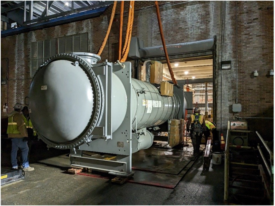
Size & Weights - The chillers and pumps were disassembled off-site into smaller and more manageable components that would fit through the existing space restraints. Each component was then delivered to the site in a predetermined sequence for each rigging segment.
Elevations & Platforms - The platform inside the door was reinforced and modified to handle the excessive weight of the equipment. The modifications included the installation of two (2) finger piers which would allow for gantries to carry the chiller barrels out over the plant floor, beyond the platform, and then lower them effectively to the floor elevation. An approach platform was also established outside the doorway to allow the chillers to be rolled through the door on skates.
Floor Obstructions and Voids – In lieu of using suspended rigging methods to carry the equipment over the obstructions, Green installed a continuous and level rigging floor throughout the plant to allow the equipment to be rolled to its proper location on skates and custom fabricated dollies.
Our rigging plans were developed internally, and the design of supplemental members and appurtenances were confirmed by third-party structural engineers.
Rigging: